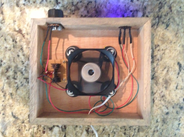
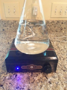
 DIY Stir Plate Project – I’m a complete novice when it comes to electronics and electricity. In my quest for better beer and personal development, I decided to build a DIY stir plate that included a voltage regulator. Based on what I read around the internet, it is possible to build a very simple and effective stir plate with nothing more than a 12 volt power supply, a rheostat or potentiometer rated for 5 watts and a computer fan. This set-up is adequate for most brewers. In my case, my stir plate may be unattended for several hours at a time. As a commercial insurance broker and claims manager, I’ve seen first-hand the destructive nature of fire. It’s fast and furious. Electronics and wooden cigar boxes might not be the best combination for a novice like me to leave around the house unattended. It seems the electrical engineers in the home brewing community generally opt for incorporating a voltage regulator into their stir plate. In my opinion, this seemed like the way to go. It’s certainly not the low cost option, but it is a reasonable cost. It offers fine tuned control, good heat management and won’t stress the electronics to the point of burning. With this in mind, I set out to build such a device. It seemed like there was a small information void on how voltage regulators actually worked, I hope this article will help fill part of this void.
The Power Supply
Lets start with the power supply. In the U.S., this device converts 120 volts of AC into a lower voltage of DC current. It’s basically a transformer. Most DIY stir plate builds recommended 12 volts or less. In addition to converting the voltage, they are rated for some set level of amperage. From what I read, voltage is the pressure behind the electron flow, while amperage is the volume of electrons allowed to move through the supply. The voltage (V) multiplied by the amperage (I) will equal the power watts of output from the power supply. My power supply is rated for 12 volts x .3A (or 300 mA), which produces 3.6 watts.
Lessons Learned & Takeaways from the internet:
- The power supply’s voltage should be at least equal to or greater than the load. (fan)
- The power supply’s amperage rating should be at least 100 mA more than load (fan)
The Power Switch
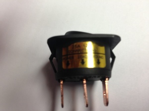 This is nothing more than a simple on/off toggle or rocker switch. I found mine at an auto parts store. It has three posts on it, one for power in, one for power out, and a third for ground. The one I chose had an LED light built in. My switch was rated for 12 Volts at 25 Amps. It’s total overkill for the circuit, but was readily available.
I connected the power supply’s out wire to the power switch’s power “in” post. The middle post of the switch is for switch’s power out and is connected to the Vin pin of a LM317 chip. The ground switch is wired-in from the total circuit out and then wired out to the power supply’s ground.
Capacitors (C1 & C2)
These optional components help smooth out the electrical current flowing through the circuit. They are not required, but everything I read and heard suggest they add to help provide a continuous level stream of current to the circuit. They store-up and release voltage to make the peaks and valley in the electronic waves into a level line.
According to my research, capacitors should be rated at x2 the circuit’s voltage. With my stir plate set for 12 volts, I selected 25 Volt Capacitors. The first capacitor (C1) in my circuit is rated a .1uF, is ceramic, rated to 25 volts, and is connected between the power switch’s supply out to ground. The second capacitor (C2) in my circuit is 1 uF, is electrolytic, and rated to 25 volts. It is connected between the fan’s power in and ground. Capacitors are polar, make sure the capacitors have their negative pole(s) connected to ground. These are the recommended settings according to LM317 Data Sheet. Note: the “u” in electronics (means micro) and represents one millionth (.0000001).
What the heck is an LM317?
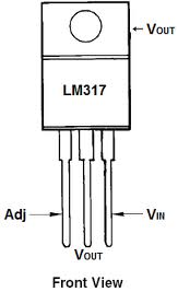 As I read about voltage regulators, most of the YouTube videos and homebrew forums & boards I visited referenced an integrated circuit (IC) called the LM317. It was at the center of many of the builds. I had no idea what an LM317 was. I pulled down the datasheet from National Semiconductor and read through it. It read like Egyptian hieroglyphics to me. So, what did I learn?
The LM317 is a pretty powerful little chip that has many applications in the world of electronics. For DIY stir plates using voltage regulation, it is the heart of the voltage regulator. By connecting the “voltage in” from the power switch/power supply chain to the LM317 “Vin” pin, the chip can be powered by the incoming voltage. The LM317 will send a set level of voltage to the Vout pin, which allows a consistant rotational speed for the stir bar. The chip itself lowers the incoming voltage by approx. 1.7 volts according to the data sheet. For example, my 12 volts power supply has approx. 10.3 volts available in the LM317. Additional voltage can be dissipated by the chip itself in the form of heat. It can sink up a few watts, but may damage the chip. By adding a heat sink to the “Vout” at the top of the chip, additional heat can be transferred to the heat sink, thereby reducing the likelihood of damage the LM317.
I still don’t fully grasp the inner workings of the LM317 with respect to the voltage out (Vout) and voltage adjust (Vadj) pins. The Vout and Vadj pins are interconnected within the LM317 itself. It’s my understanding that the bulk of the power is delivered to the fan (load) through the Vout pin. The “Vout” pin is connected to the “fan (load) in”. The Vadj pin regulates how much voltage is sent to the Vout pin.
Resistors (R1 & R2)
R1 – This component is a fixed resistor and rated for 120 ohms w/ .25 watts. Most LM317 chips data sheets/schematics show a resistor of 220 ohms for R1. The 220 ohm was evidently pulled from another IC chips data sheet which was designed to work with voltage greater than the LM317. This will work, but will change the pot needed at R2. This resistor is placed in series with the LM317’s Vout Pin, and in parallel with the LM317’s Vadj pin. This allows R1 to remain at a constant 1.5 volts during normal operation.
R2 – the potentiometer (POT) is a variable resistor that is rated to introduce a certain range of resistance in the forms of ohms. The pot basically lengthens the amount of resistive material a current must travel through within it’s inner workings. According to my research, one pot with solid performance for a stir plate was a 1,000 ohm linear rotary pot. This pot is placed in series with the 120 ohm resistor at R1. I also had to pick up a knob for the Potentiometer.
Why use 1/4 Watt Resistors?
The Vadj pin is a crucial part of the LM317’s operation. It acts as a reference voltage for the LM317. It runs at a constant 1.5 volts at very low mA levels. According to the LM 317 Data Sheet, the Vadj pin has typical amperage (I) of 50 uA, with a max of 100 uA passing through. Assuming all 12 volts at maximum amperage were passing through the Vadj pin, the wattage is only .0012, or approx. 1/800 of a watt. (12 volts x .000099 Amps) As such, the resistors on this part of the circuit of 1/4 Watt are more than sufficient to handle to the wattage. I was able to use a potentiometer rated for 1/4 Watts as well. All of the voltage on the Vout pin is referenced through this Vadj pin. This reference voltage is a function of the resistance on the resistors at R1 & R2.
R1 & R2 – Together
By connecting the Resistors (R1 & R2 ) to the LM317’s Vadj pin, the resistors are able to add variable resistance (ohms) levels to the Vadj pin. The changing resistance is what tells the LM317 to increases or decreases the voltage to the Vout pin. The more resistance encountered on the Vadj pin, the more voltage is directed out of the Vout pin. The voltage out for the Vout pin is found with the following formula:
V out = 1.25 * (1 + R2 / R1 ) + 50u *R2
The table to the right shows the numbers from my Voltage Regulator derived from these formulas. I’m using very low values for R2, so the [ + 50u *R2 ] part of the equation above is close to zero and has minimal influence. Note: + 50u equals a decimal value of 0.000005.
To calculate Ohm’s values for “R1 & R2”, the formula is (R1 * R2) / (R1 + R2). For example: (120 * 1,000) / (120+1,000) = 107.15 ohms. My table has a typo showing 107.5, it should be 107.2.
The purposes of these two resistors, placed in series on the Adjust part of the circuit is to introduce a certain range in ohms of resistance to the LM317 Vadj pin. R1, a fixed value resistor, is positioned in the circuit to produce a minimum voltage/amperage to the LM317 and prevent damage the chip itself. The LM317 chip requires a minimum of 10mA of current. R2, a variable resistor, offers changing ohms values. Together they can produce a voltage range of 1.26 to 11.67 volts on my stir plate. However, the LM317 only provides 10.3 volts on my circuit, so I’m losing some voltage by limiting my maximum range of resistance to about 870 Ohms on R2. In essence, I’m losing use of the top 13% of the pot. Not a huge deal, my stir plate can still run the stir bar at 10.3 volts quite well.
Fan (The Load)
The fan is used to spin the magnet/stir bar assembly. I used a 80mm, 12 volt, .18 A (or 180 mA) computer fan salvaged from my garage. The fan will pull as much amperage as it needs to run. It was recommended to have an additional +100 mA of additional head room from the power supply to allow extra power draw at fan start up. The fan and headroom add up to 280 mA. I have a power supply of 300 mA, so it meets these requirements.
The fan’s “power in” wire is connected between the “Vout” pin, after the “1 uF” capacitor. The fan’s “power out” wire is connected to “ground.”
So how to you wire this thing?
The attached drawing shows how I assembled the electronics in my voltage regulator. I had a hard time deciphering how voltage regulators were wired. I pulled this set-up from various web sources. I hope it helps add some clarity to brewers willing to build one. I also wanted to have a record of how I built this, should I need to build a new one in the future. In an effort to help my fleeting memory, I crafted these schematics based on research from numerous sites, by people much more capable. This first image is the usual LM317 schematic and I’ve added some numbers and letters to help mark the nodes.
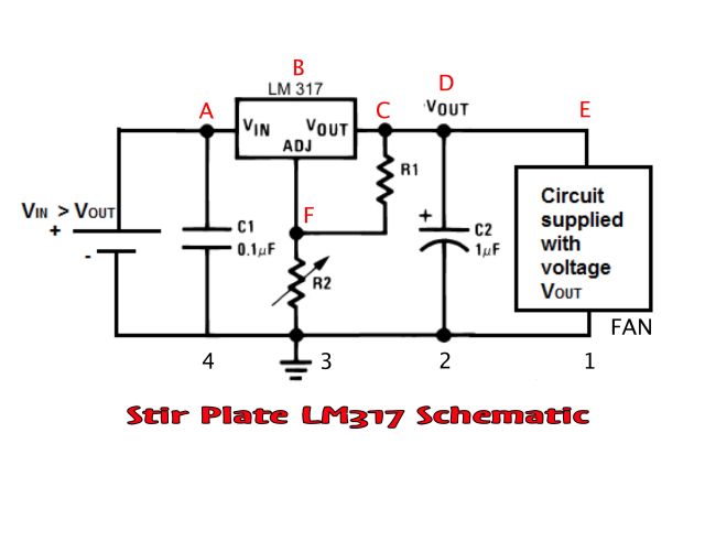 This second image is the electronic build of the voltage regulator and other stir plate components. I’ve ID the nodes to match the schematic above.
Watch this video to see how the board is built – Click to Play
Here are a couple of photos showing The Sparre Brewery’s stir plate in action. Hope these visual help. This is the build I used on my stir plate, with good results!
INFLUENTIAL LINKS
The following links were very helpful in this project. My thanks to those who shared their knowledge and insight.
Box Build
- Sean Terrell’s Stir Plate Article
- BYO Article – Build your own Stir Plate
- Stir Starters
- Computer Fan Tweak Article
- BrewBoard Article
Voltage Regulator & Electronic Calculators
- YouTube Video – How Voltage Regulators Work
- LM317 Data Sheet – National Semiconductor
- LM317 Data Sheet – Second Version
- Learning About Electronics – LM317
- Inner Workings of LM 317 Article
- Voltage Calculator
- YouTube Video – How Pots Work
- R1 & R2 Parallel Resistance Online Calculator #1
- R1 & R2 Parallel Resistance Online Calculator #2
- R1 & R2 Parallel Resistance Online Calculator #3
- Wattage Calculator
- LM 317 Electronics Article – Paranoid Troll
- HomeBrew Forum – Rheostat vs Potentiometer
- Northern Brewer Forum – Article
Rare Earth Magnets
Where to get parts


